CTC
212 – Microstation V8i
Student
Examples of Rendered Drawings (Fall 15)
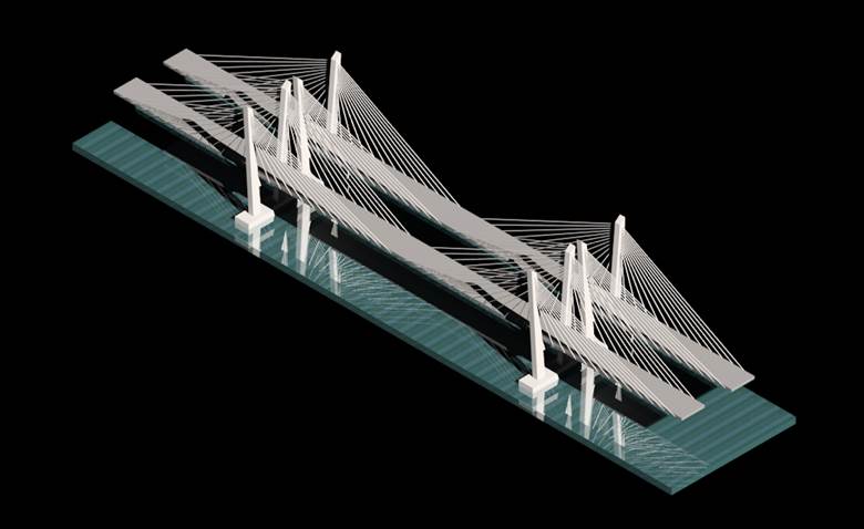
Figure 1
Rendering by Judge M.
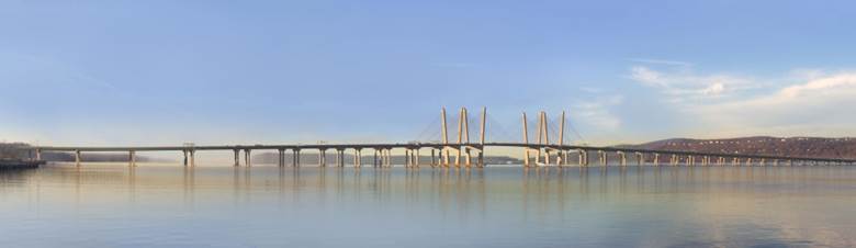
Figure 2
Professional Rendering
Judge M. (Civil Engineering)
The
project I choose to draw and render is based on the main span of the new Tappan
Zee Bridge in New York that crosses the Hudson River, connecting Westchester
and Rockland counties. The main span of the bridge is 1200 ft. long and is supported by a
cable-stayed design that connects the roadway to two 419 ft. tall chamfered
towers. The main span rises 139 ft. above the main channel of the Hudson River.
I chose this bridge because it is a major project going on in New York State and
it was not too complicated to re-create.
The
cable-stayed design refers to a type of bridge design where the deck is supported
by straight cables attached to the towers. The towers are built first and the
deck sections and stays are attached progressively. Cable-stayed bridges allow
for long bridge spans.
The drawing is not totally to scale. I could only find some of the main dimensions
such as the height of the towers, the main span length, the height of the span
above the river, and the width of the roadways, 96 ft. and 87 ft. I made educated
guess based on the dimensions I had to complete the drawing.
The new Tappan Zee is on track to be
fully opened in 2018 while remaining within the $3.98 billion budget. More than
5,000 people have worked on the project so far and Tappan Zee Constructors, LLC
has utilized more than 620 New York companies to help build the new twin-span
bridge.
To create my drawing I used shape tools and then used the extrusion tool to create solid shapes. Once my structure was done I was able to attach materials to make my drawing look more realistic. The only thing that I had trouble with was attaching lighting to my drawing. I wanted to attach lighting to the towers to show how the bridge will be lit up at night, but I was unable to get the lighting tool to work.
Isometric
View (top); Front view (bottom)
Edcel
G. (Civil Engineering)
For this project, I decided on doing a simple one story house with a balcony, 12 foot driveway, and a small front lawn. My cousin recently bought a house in Illinois and I was inspired by how gorgeous the house was. So during the week that this project was given, designing a house was the first idea I had in mind and went with it.
Overall this project was moderate in terms of difficulty. At first, I was having difficulty with the global axis drawing but I searched for Microstation key commands on the web and the drawing process was a bit easier from there on. One thing that slowed down the drawing process was making sure the correct levels were utilized in drawing each material. I just had to be cautious with attaching levels and making sure the correct material was attached to the appropriate level.
Note: A clear glass-reflective material was attached for the windows; that’s why it looks transparent.
Gabriel
S. (Civil Engineering)
For this project I decided to draw a football field and stadium for SUNY Polytechnic Institute. I chose this project because I like football and would like to see SUNY Polytechnic Institute make a football team. I started the project by creating the field because it was the central part of the drawing. I found that it was difficult to render materials in a realistic looking way. I also found it difficult drawing the football field lines and goal posts because of all of the specific dimensions required for a NCAA football field. What I found easy was the ability to use certain commands to cut the work down. Basic commands such as mirror, copy and move as well as 3D specific commands like solids by extrusion were very useful. This project was difficult and time consuming but very fun because it was based on something I enjoy.
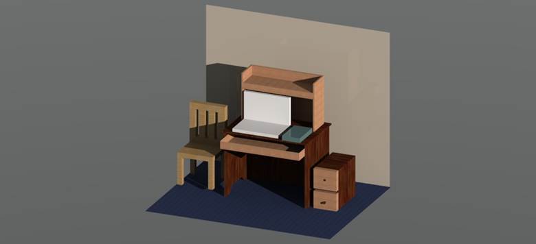
Jonathan
S. (Civil Engineering Technology)
For my final project I decided to recreate the desks that we get in the dorms. To start off I used mainly the basic 3D tools that we have used earlier in the year such as slab, extrude, block, shell, and multiple others. However in order to truly get the design that I envisioned I needed to play around with a couple different tools that I never used before. Furthermore, I added a chair and another drawer in order to fill space, and add more complexity to my project. Finally, the visualization tools helped bring the whole drawing together, and made it look realistic. By adding light sources, the shadows added more depth and really gave me the outcome I was looking for.