CTC
212 – Microstation V8i
Student
Examples of Rendered Drawings (Fall 2016)

Christian
F. (Civil Engineering Technology)
For my final
project I decided to create a simple EXIT sign with the flashing red letters. I
was inspired to do this for my final project because it was a simple enough
drawing to prove that I know how to create 3d shapes, extrude, and cut them
into the drawing. The project overall
was very simple because the sign is composed of one large 3d box, a cylinder, a
rectangular prism, and the extruded letters into the box. At first I had
difficulty showing how an exit sign would be able to suspend from a ceiling,
which is why I created a small cylinder on top of the box which holds up the
rectangular prism that is connected to any ceiling by screws. The drawing was
complete but what slowed me down the most was the rendering because it was
difficult to get two different materials on my drawing. If I used plastic- gray
the whole sign would be gray. So I had to create the letters of the EXIT sign
on a different level. That way I was able to assign a material based on the
levels of the drawing.
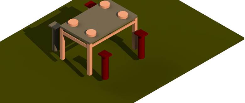
Michael
L. (Civil Engineering Technology)
For my final
drawing I chose a table. Although it’s
rather basic I tried adding some nice detail to it. I used tools that I have
learned from the first day to the last; that’s what I really like about this
project. Even though it was just a table I used different tools to get my table
done. Such commands include, but are not
limited to: Place Smart Line, Place Line, Place Block, Place Rectangular
Polygon, and Place Circle within the Drawing Toolbox; Solid by Extrusion,
Fillet Edges, and Mesh from Element within the Solid Modeling Toolbox. After
constructing the model, I utilized the Render Toolbox and Light Toolbox to add
a realistic appearance. These two toolboxes may be found under Tools, then
Visualization. The only problem I had was with the rendering. I assigned the
wood I wanted to my table but when I go to render it the actual design was not
large enough to view. So it looks like it is just one plain color but when you
scroll in to zoom in you can see the actual design. There were so many tools I
used to accomplish this drawing. I tried using all of them and when I was
finished I couldn’t think of any more tools to use. Array really came into use
for the legs of the tables, chairs, and plates; that was the tool I used most
and it definitely made things a lot easier and quicker.
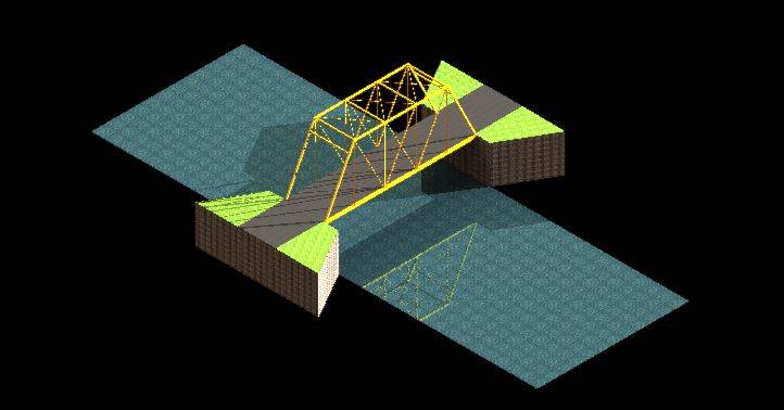
Daniel
C. (Civil Engineering Technology)
For this project I decided to draw a bridge that is part of my local community. I chose to draw this because I have been fascinated by this bridge since I was a young kid. It is one of the many things that influenced me to study Civil Engineering. This project took a while to draw because it was hard to find a good scale for it and make it look realistic. I used some of the many lighting and shadow features to also bring the realness to the drawing. I also used a lot of the solids modeling to construct the bridge and foundation. I assembled the foundation and the actual bridge separately and put the bridge in place as my final step. This was drawn using MicrostationV8i.
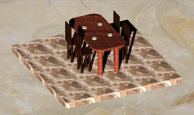
Anthony
L. (Civil Engineering Technology)
For my final
project, I decided to draw a dining set with a marble floor. To start off, I
mainly used the basic 3D tool, extrude. However, to obtain the design that I
imagined I needed to tinker with different tools that I never used before, such
as placing lights. Furthermore, I added chairs and plates in order to fill some
space and make the project a little bit more involved than simply drawing a
table. I also added the marble floor, which really complemented the dining
table. The visualization tools really helped the image come to life, making it
look realistic. By adding light sources, the shadows added more depth, and
based on the long shadows you could have imagined the dining set to be placed
in a morning sunrise or evening sunset.
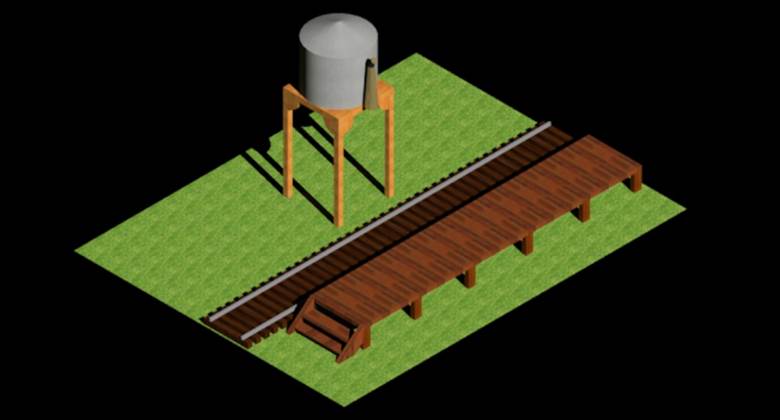
John
G. (Civil Engineering Technology)
I made a small
town train station that you would see in the late 1800’s. I used Standard gauge
track which is the track that most all the railroads use in the United States. The
rail type during the 1890s was set at 40 lb. per yard. The water tower is a
scale water tower that the defiance coal company used in New Mexico during this
time period. It was able to hold 8000 gallons of water that fed the two steam locomotives
that ran on the short line. The platform is an accurate representation of one
of the originals.


John
D. (Civil Engineering Technology)
For my final project I submitted two images. The first being a sign very similar to the kind we have in pediatrics unit in the hospital I work at. The sign is given the illusion of floating letters and is usually accompanied by silly colors or cartoon characters. The sign is given the illusion of floating letters with the use of fishing line, but the children can usually not tell as they are lower to the ground than adults and the sign above their heads as they walk in. This was pretty challenging for me to accomplish, as was the rounded corners of the sign. Overall, I felt like we learned a lot in this class, and looking back at what I was challenged to do in the beginning has since become much easier, it is actually a pretty rewarding feeling. The second project I submitted was another idea I had, and that was the Philadelphia Flyers logo. Hockey is something I am very passionate about, a really fun hobby I share with my friends, and it was a fun little side project to work on. Unfortunately, it did not come out as great as I had hoped because I was not able to get the colors correct when extruding it. Regardless, it was still fun to do but that is why I chose to submit it. The pediatrics sign is my actual project however.
Richard C. (Civil
Engineering Technology)
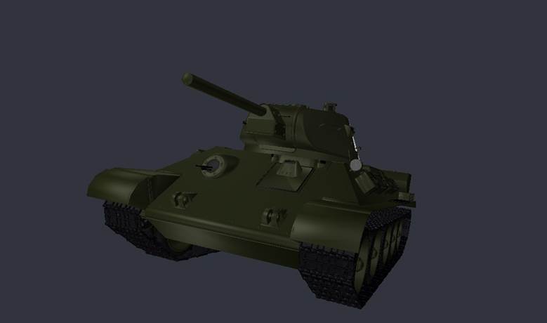
My little brother
loves World War 2 and the history behind it, so I decided to try to take
some 3D Models from his favorite game and import them into Microstation
and then work from there. The tank is a Soviet T-34. It is not exactly historically accurate but I
tried my best to make it look like a real one. I enjoyed using the
elements on Microstation and other programs to put
this together as one. The hardest part was trying to import and export different
items into the 3D file; the program might freeze and I would lose my work or it
would not work. All said and done it was lots of fun and I am proud of
it.