CTC
112 – Microstation V8i
Student
Examples of Rendered Images (Fall 2018)
E. Zan (Electrical Engineering Technology)
-Senior
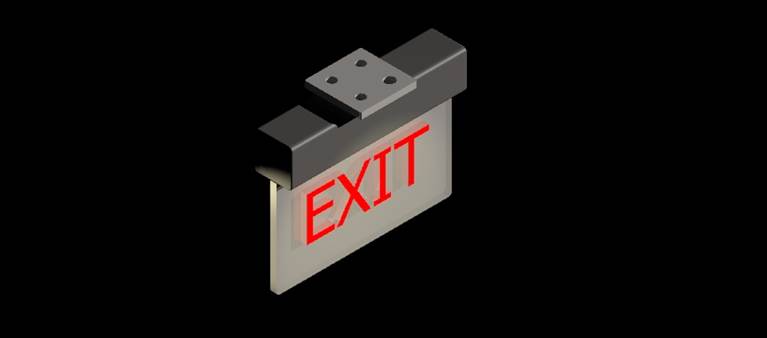
For my 3D drawing, I decided to draw an exit sign. I choose
to draw the exit sign with glass material because it allowed me to play with
properties of the materials. Instead of applying the pre-installed glass
material, the material properties such as transparency, brightness, and
reflectivity were adjusted. The mounting unit for the exit sign is made out of
metal/plastic. I also added a spotlight to create dynamic visual on the final
render. The glass material has transparent property where the light shines
through. The metal mount shows the metallic property as the light bounces on
it. The text “EXIT” is not just text but it is an element where the property
was applied. I adjusted its property to react vibrantly when the light hit. I
also drew out the model close to a real-life scale from an exit sign dimension
and diagram found online.
E. Lam (Civil Engineering Technology)-Freshman
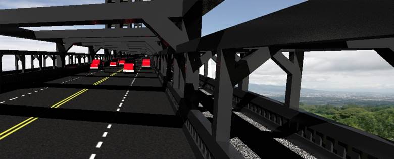
I chose to draw a bridge as my 3D final drawing because
back at home I rode my bike a lot and I always passed under a bridge and I’ve
been on a lot of bridges, so I have a really good idea of what they look like.
I started with the road first because a bridge is meant for things crossing it.
I then made a walkway and started making beams. A lot of the shapes were simple
because they were just slabs. Enough slabs in the right place created a lot of
detail. I also had to create a lot of levels because there were many different
materials I had to work with. My bridge was heavily influenced by the Brooklyn bridge because it is was a bridge where people are permitted
to walk on. After I made a small part of the bridge a lot of it was copying,
the tool allowed me to key in as many copies as I wanted. After copy I made one
structure of the bridge, this structure represented what was holding up the
road above water. After one half was made all it took was a mirror. I then
created land, a beach, and water. I also wanted to see what a car would look
like compared to my bridge, so I created small little cars. Cars can be extremely
detailed and complicated, so I made a simple red block car. The most difficult
part was creating the first 100 feet because I had to work with multiple views
to make the bridge look detailed and organized. A lot of the commands I used
were basic; easy to learn but hard to master. The car looked simple but it was
fairly hard to make because I wanted some detail on it.
S. Gonzalez (Civil Engineering)-Freshman
For my Final 3D drawing I decided to create a bridge.
Being that I am majoring in Civil Engineering I felt building a bridge of my
own would be appropriate. It was a bit difficult to get started at first, but
once I got the hang of using slabs and solids and molding them to how I wanted
the drawing progressed much faster. Most of the modeling after I laid out the
foundation was copying, rotating and moving the solids to make it look like an
actual bridge. The visualization and placing the material to make it most look
like a bridge was a lot of trial and error, but I finally found one I felt look
the most like the material of a bridge. I drew the yellow line on the roads
which mostly consisted of using the copying element. Overall it was a very
informative class on the basics of Micro stationing and teaching me enough to
create a a 3D drawing such
as this one.
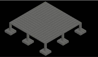
J. Lavelle (Civil Engineering Technology)-Senior
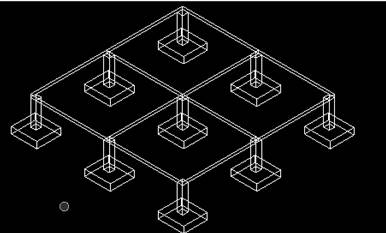
I chose this footing and slab structure because I am in
the concrete design and we were doing footings. The measurements for the footings
were chosen from a homework we did in the concrete design class. The footings
on the rendered version from the middle point to the far back points do not
show up due to the fact that the back footings are under the slab of concrete. So
to show that the back footings are there I added a view showing the outlines of
the solid. I mainly used the solid modeling command slab solid for both the
footings and the slabs. The material chosen was the concrete one in the
material section of the material tab for concrete and pavement.
The footing measurements are length 6.5’, width 7’, and
height 21”. The footer column measurements are length 1.5’ length, 1.5’ width
and height of 7’. The slab measurements are length 20.75’, width 20.75’, and
height 9”. There are four footings that are connected to each slab at each
corner and there are five footings that hold the force of multiple slabs.