CTC
312 Student Examples of Rendered Drawings (Spring 01)
J.
Bruzee
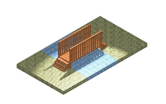
I decided to
“design” a bridge. The banisters, top
railings, floor side rails, and each of the floorboards were placed using the
“place slab” command. After the main part
of the bridge was laid out I decided to lift the bridge off the ground and add
stairs on each end. I placed two slabs
that could be used for grass and a slab that could be used for the stream
running under the bridge. The last
thing I did was to chamfer the end handrails and the edge of the steps on the
bridge. I thought this was a really fun
project to do. When I started I was not
sure that I could finish it, but now that it is done, I am really pleased with
the results. You are able to see each
of the individual boards in the floor of the bridge and you are able to see
through the handrails. Every element of
the drawing works well together.
M.
Colby
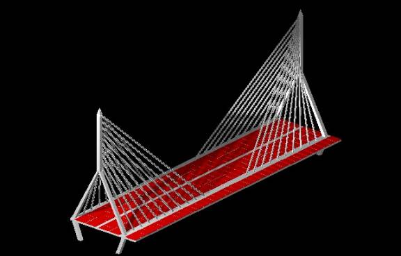
This is my
interpretation of an April sunset, seen through the center span of the Charles
River Bridge. This is an amazing new
bridge that is currently being constructed on the Central Artery, which cuts
through the heart of Boston. My
previous employer was responsible for the inspection of the pre-cast concrete
panels that made up the driving surface of the center span. I was personally offered the 18-month job of
inspecting these panels where they were made, in a pre-cast plant in
Virginia. I turned it down to go back
to school. And here I am.
I started with the pre-cast concrete panels that make up the driving surface. I have plans for these, so I drew them to the nearest foot. The other dimensions were inferred. The slabs were left red to show contrast. The only difficult part was crunching numbers to figure out precise locations.
S. Aichner
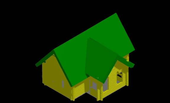
The object I chose
is a basic log home design. The
foundation is a concrete slab; the walls are 9-inch diameter pine logs. The interior is designed for the possibility
of one to four bedrooms. The center
section is designed to house the kitchen in the backside and the living room
area toward the front section. Not
shown in my design is the two-way fireplace that divides the kitchen and dining
areas from the living room. I had a
great time creating this project. My
experience doing this has greatly increased my respect for those whom do
three-dimensional design with computers.
L. Munson
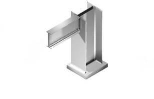
For the final
project I decided to draw a beam-to-column flange connection; and at the end of
the column, there is a base plate. The
beam and column were built using smartline and accudraw. The beam was drawn in the front view and the
column in the top view. Then I drew an
angle that was used to make the connection from the beam to the column. To get two that were exactly the same I made
one and then mirrored the original. I
moved the objects into the right place once they were all drawn. I added a base place to the bottom of the
column and constructed a fillet to make a weld at the bottom of the column to
the base place. The material that I
used was iron because the material palette did not have steel to select
from. Source and global lighting were
used.
B. Lucarelli
I designed a 6’ x
7’ concrete box culvert with reinforcing bars in the concrete. About 90% of the project was done in the
front view, and when it came time to extend the materials and render, I worked
in the isometric view. The box
structures were added first and the reinforcing bars were added last. I used global lighting to show the
shadows.
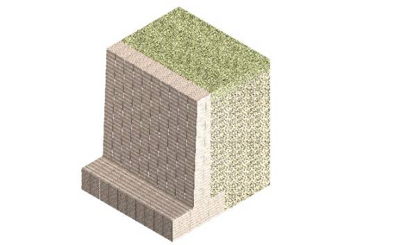
D. Cron
I put in many hours
on this project. I had problems setting
the active depth and the display depth.
I think that the source of my trouble was I missed most of the
presentations on 3D topics due to circumstances beyond my control. My daughter decided it was time to be
born. Once I was able to set the active
and display depths where they needed to be, the rest of the drawing was pretty
simple. The material used for the
retaining wall was block-split face from the masonry palette.
P. Gleeson
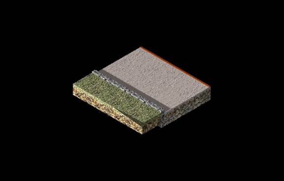
My final 3-D
drawing represents a cut section of a roadway.
I created boxes to represent 18” of gravel under the roadway, 4” of
screened gravel, 4” of binder, and 2” of topcoat. Boxes were also used to represent the curb, grass, and soil under
the grass. It was hard to find a
material to represent the asphalt for the topcoat. I selected the “fine stucco” material under the “surfaces”
option, changed the base color to a dark gray, and the secular color to
gray. I used global lighting, choosing
the City of Boston. I also applied a
“point light” to the bottom of the 18” of gravel. The combinations of these two lights created the effect of the
afternoon, casting a shadow from the left side of the drawing to the right. Overall, I feel that this drawing did not
come out as well as I hoped. I was
disappointed that Microstation did not have very many options for surfaces
related to highway construction.
However, I was happy with the end results of the lighting effects. After completing this drawing, I do feel
that I have a better grasp on how to use the 3-dimensional tools in
Microstation.
B. Albanese
I found the idea for my final project while I was estimating a project at work. It is a section of footer, foundation wall, slab, floor joists, sheeting, and a perforated continuous drainpipe surrounded by crushed stone. The first task that I found difficult was making the adjustment from x-y axes to x-y-z axes. I had trouble figuring out what dimension went in what order, and kept finding that the drawing looked correct in one view, but wrong in another. The second problem I faced was getting the lighting correct; it either appeared too bright or too dim. This was by far the hardest drawing skill-wise that I have ever accomplished, and I feel that it turned out extremely well.
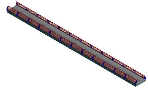
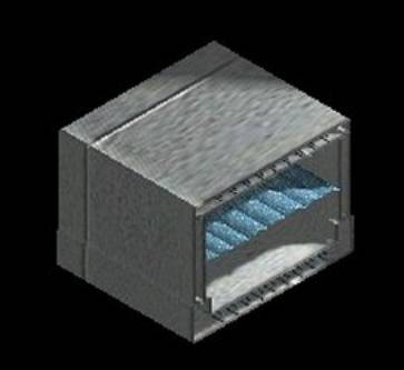
C. Roberts
Rendered drawing of a bridge deck. Note the guide railing.
SUNYIT Home | Baran's Classes | ISET Home | E-Mail S. J. Baran