CTC
312 Student Examples of Rendered Drawings (Spring 02)
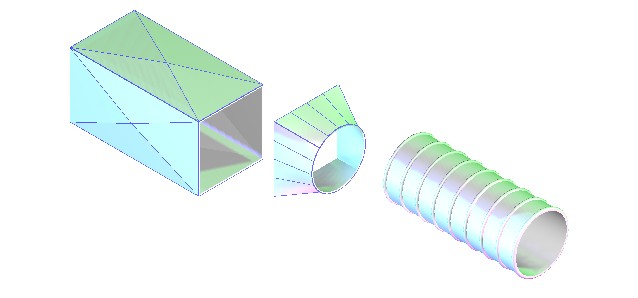
Courtney
C. (Mechanical Engr. Technology)
I drew a piece of
square duct transitioning to a piece of round duct. I used a 24 x 24 inch square duct and a
20-inch spiral duct. I needed to figure
out a way to construct the transition with all the proper curvatures and
angles. The square duct and transition
were created by creating separate surfaces and stitching them to make a solid
part. The spiral duct was created by
drawing a polyline in the side view with the
thickness and length of the object defined.
I then revolved the polyline on a circular
path. There was not a material for steel
so I had to choose another material for representation. I ran into many problems creating my surfaces
and joining them all together to form the solid. The book did not help much. I ended up reading many of the help files and
using trial and error to create things the way I wanted.
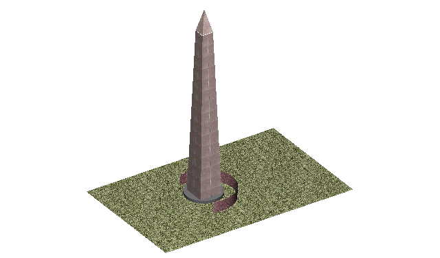
Ismail Z. (Civil Engr. Technology)
The world’s famous
monuments and architectural sites have always inspired me. One of my future long-range plans is to see
as many famous sites as possible. For
years, I thought my first visit would be to Giza
Pyramids in
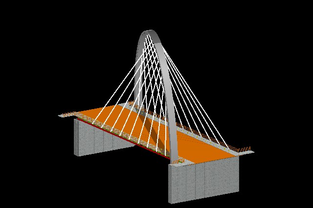
Muhammad Z. and Genadiy L. (Civil Engr. Technology)
We chose to draw an
architectural marvel, the Hulme arch bridge located
in
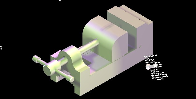
Daniel M. (Industrial Engr. Technology)
For my final
project I chose to draw a 3-D solid model of a machine vise. A vise is made of solid steel and is used in
industry for the machining of small and intricate parts. The place cylinder and place slab commands
were used to create many of the parts. I
used the solid editing commands for creating the chamfer and fillets. Also, I used the union and subtraction
commands on the parts that needed to be together. I used two main lighting schemes, both
distance and spot lighting. One of the
spot light positions can be seen on the rendered drawing.
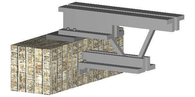
Gerald H. (Civil Engr. Technology)
My final project
consisted of drawing a simple beam connection.
The project was more difficult than I first imagined. The connection I modeled was taken from an
old structural steel book. The most
difficult parts of this project were modeling the beams that were cut away and figuring
out how to use the texture and lighting.
SUNYIT Home | Baran's Classes | ISET Home | E-Mail S. J. Baran