CTC
312 Student Examples of Rendered Drawings (Spring 05)
Michael
B. (Civil Engr. Technology)
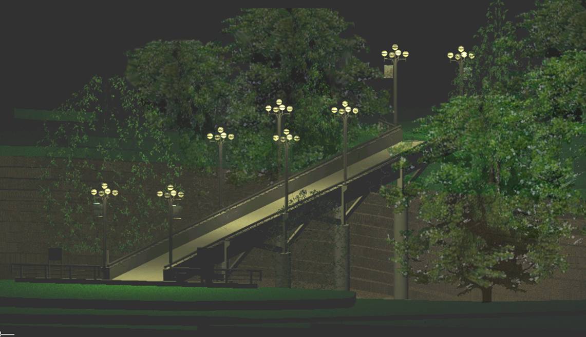
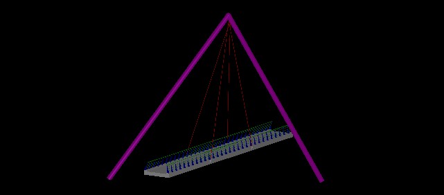
This drawing is a
scaled representation of the SUNYIT bridge that links
the academic buildings to the campus center and dormitories by allowing people
to cross the valley and creek below. I
chose this project because I wanted to create something that people would
recognize. This was a simple drawing to
create, primarily using the extrude command along a path, and several basic 3d
shapes. The site was somewhat time
consuming to create because the topographic map had to be manually redrawn
before bringing the image into the program, scaling it, tracing it, and extruding
the elevations. The final renderings are
actually done in AUTOCAD, because I had a lot of trouble trying to create new
textures in Microstation. I learned how easy it is to interchange
drawings back and forth between the two programs. I also learned a lot about simulating
lighting that I did not know before.
Kelby
M. (Civil Engr. Technology)
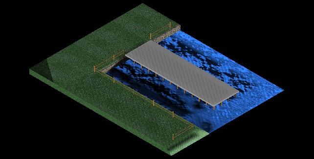
The project I chose
to work on was a pier. The type of field
work that I am looking to go into is working with piers and other waterfront
structures. I was able to incorporate much
of my knowledge of 2-D design and adapt it into the 3-D realm. I found trying to get elements placed in the
proper place took a bit of practice and working with multiple views at
once. Rendering took the most time. I have discovered there are millions of
possibilities of lighting, shading, and texturing one has to account for. I feel as though if I had more knowledge of
rendering, my design could have been more aesthetically pleasing. Overall I feel very proud of the design being
my first to use rendering and multiple elements.
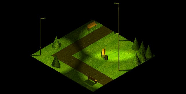
Aaron G. (Civil Engr. Tech)
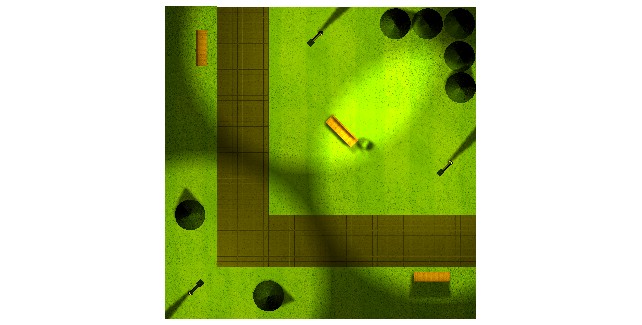 Since the beginning of the
semester, we have been working on 2D and 3D drawings in Microstation. The final project that I chose was a park
scene. I started out by making the slabs
for the grass and the walkway, and giving them texture. I then added street lamps with lights so I
could create the ambience of a park. I
then added the trees, benches and garbage can.
The hardest most time consuming part of this assignment had to be
attaching textures, adding the proper lights, and rendering. I had to position the lights within the
street lamps so that they gave the proper shadows and details to the
drawing.
Since the beginning of the
semester, we have been working on 2D and 3D drawings in Microstation. The final project that I chose was a park
scene. I started out by making the slabs
for the grass and the walkway, and giving them texture. I then added street lamps with lights so I
could create the ambience of a park. I
then added the trees, benches and garbage can.
The hardest most time consuming part of this assignment had to be
attaching textures, adding the proper lights, and rendering. I had to position the lights within the
street lamps so that they gave the proper shadows and details to the
drawing.
William
V. (Civil Engr. Technology)
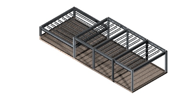
For my final project
I chose to design a 3D model of the major members of a steel structure. The design is loosely based on a maintenance
building our capstone group designed during the semester. The framing supports a high and low
roof. The members drawn for this model
are: joists, beams, girder, columns, slab and short wall. The connections for the members were not
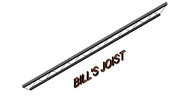
drawn. The joists were the most complex
members. The different members were
constructed in separate layers. One main
problem was lighting the entire structure without “washing out” the steel
skin.
Stephanie
W. and Nick R. (Civil Engr. Technology)
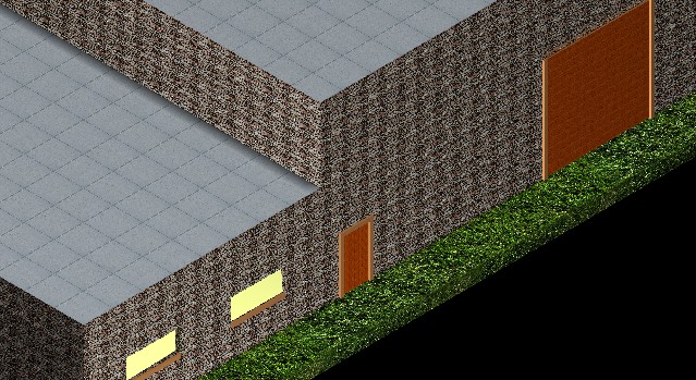
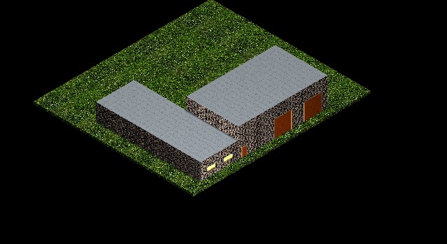
This 3D drawing is
an illustration of the maintenance building designed during the capstone
project. The large bay garage doors and entrance door were created as blocks
cut through the slab wall. The windows
were drawn in the same manner. The
lighting used to illuminate the image was a modification of the existing global
lighting and one area light, which was placed just off the front left
corner.

Tom
M. (Civil Engr. Technology)
My final project is
a timber frame. Blocks were added to
simulate the floor slab and grass. The
columns, knee braces and roof rafters were created by placing two dimensional
blocks and extruding them to create three dimensional elements. The post dimensions are 10”x10”, the knee
brace dimensions are 4”x6”, the girder dimensions are 6”x12”and the roof rafter
dimensions are 10”x10”. There are five
spotlights and two distant light placed around the structure. Solar and ambient lighting is also
included. Applying the lighting effects
was the most difficult task of this project.
I found that building elements on separate levels can aid in 3D design
work.
Dave
L.
My final project is
a drawing of the