CTC
312 Student Examples of Rendered Drawings (Spring 06)
Duane
C. (Civil Engr. Technology)
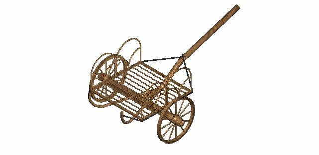
The object I have drawn and rendered is based on an Irish
Chariot. I had two models to work from, both of which were developed based on
evidence found in bogs in
Construction is fairly simple. Three foot diameter wheels, a substantial fixed axle between them, and a bent pole from the axle to the yoke of the harness. What is unique is the next part, which is a primitive suspension system. From the pole there are two smaller bent wood pieces (suspension beams) that branch off in a v-shape from the pole, through the axle, and behind and rising higher than the sitting/standing platform. These are meant to be somewhat flexible. The sitting/standing platform is suspended from ropes that are tied to the pole, go to the corners of the platform, and are tied to the suspension beams.
Now, the drawing shows the suspension beams passing through the bottom of the axle, which seems unlikely to me, as that is the tension flange. So I have run them through the top part of the axle. (It was a historian who did the drawing, after all.) My drawing is not intended to be a copy of either of the drawings I worked from. It is, instead, a working drawing for me, as I intend to build a model of this chariot.
I did most of the drawing by drawing single lines, then using them as paths to extrude from. In some cases, I used 3-D primitives, particularly the slab. I used the volume of revolution tool for the tire. The spokes I had some trouble with, because the machine was giving me a hard time about rotating through the angles I wanted. Eventually, I used the mirror tool to get around that.
The things I found difficult in drafting this project were learning to use the extrusion tools and the volume of revolution tool. I also had to develop my own dimensions from the drawings in the pictures I have, and then translate it into 3-space. I could not invoke the volume of revolution tool and then select a grouped object. So I tried to rotate the individual pieces, which worked fine for most of them, but some of the smaller pieces simply refused to be rotated about the axis I chose. Eventually I discovered that if you select the grouped object before invoking the revolution tool, you can use it on a grouped object.
Jason
M. (Civil Engr. Technology)
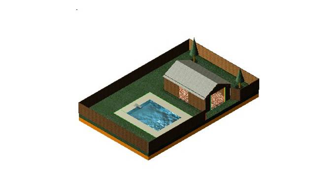
For the final
project I chose to construct a garage.
Once I had the garage and ground constructed I created an in-ground pool
with a wrap around concrete sidewalk and diving board. The operation that I found to be the hardest
was finding the right ACS coordinates to place the fence section to the
garage. Working in 3D is very tricky and
can be very time consuming.
Kevin
K. (Civil Engr. Technology)
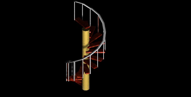
I searched the
internet for something with dimensions that I could draw to scale. What I found was a spiraling staircase. I used the construct array method set at 25
degrees to creat the multiple stairs going around the
post. The post was much easier to
construct; I just used several cylinders to build up to the top one. Drawing the hand rail was a little tricky; I
used the 3d cylinder method to construct it.
The post was rendered in brass, the steps were rendered in high gloss
bur, and the hand rail/posts were rendered in aluminum.
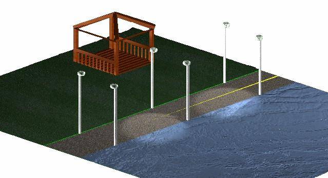
Edward
T. (Civil Engr. Technology)
My drawing design
was based on the idea of southern, public “roadways”. In