CTC
312 – Microstation V8XM
Student
Examples of Rendered Drawings (Spring 07)
Jeremy
Williams (Civil Engr. Technology)
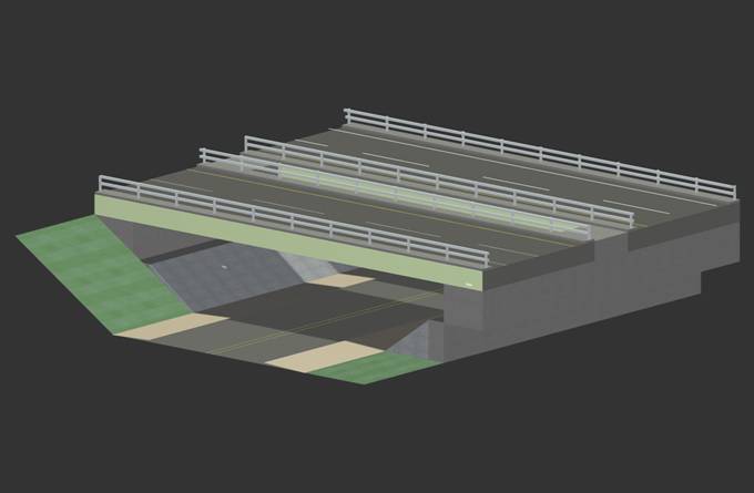
The structure I chose for the final project was the route 8
bridge over Pinnacle road in
I started my project by taking pictures of the bridge from all angles and using the lanes of the road as a scale to determine the geometry of the structure. I started drawing with the bridge decks and moved my way down, constructing the support and eventually the roadway underneath. I found the best and most efficient way to work was by using many layers and breaking things into many pieces by placing them on separate layers. This made it easier to manipulate things at different depths which can sometimes be a problem and also made rendering much easier because a whole layer could be rendered in the same material.
The most difficult thing that I found was in doing more detailed work like the guardrail. It was hard to maintain the correct depth and work on only one rail at a time. Also the grass embankment was difficult to construct. I tried to make a more realistic looking bank that curved as well as being elevated. This was the most difficult task I encountered and I was not able to figure out a way to do it.
Brian
Russell (Civil Engr. Technology)
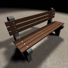
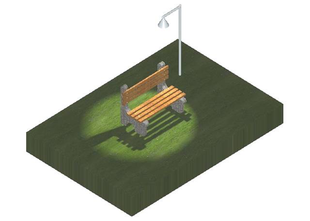
The scene that I have drawn is a specific part of a park. I originally chose the bench as my main object to draw from a picture of a bench that I found online (see drawing on left). The bench itself was interesting enough to spend the time on creating and once I finished the bench I added the light pole and light to cast a shadow with the park grass underneath it all. I chose the bench because this object in itself took advantage of many of the 3D drawing tools. The grass and light pole were on my mind when I first saw the bench and I was able to create them as part of a little park scene in 3D.
I started off with experimenting in the different views by drawing with 3D primitives and seeing how they looked. I drew a few slabs and then experimented with drawing slabs on top of them or under them to get a feel for how I would construct the complex shapes (the supports on the bench). I then decided to conquer the supports first. I drew a slab of a certain length and then drew a taller thinner slab on top of it. I used the union tool under the 3D drawing options to join the two slabs together. I then used the blend feature to round the edges of the support. Next, I used the sphere tool under 3D primitives and drew a sphere in the center of the bottom of the support. I then used the difference tool which cut the sphere out of the support. After this I used the chamfer feature along with the blend feature at the interior right angle of the support where I joined the two slabs to give it a rounded effect. Once one support was done I just copied it so that I would have one for each side of the bench. Next, I worked on the wood planks that you would sit on, which was a simple slab drawing tool and then I used the move and copy tools to create three more. Then I did the vertical planks with the same procedure just making sure that the slabs were drawn in the vertical direction. Using the different views really helped in this step. Next I used a cylinder tool for the bolts that go down into the wood planks. I simply drew one bolt and then put it in the center of wood plank and the support and copied it 13 more times and placed them in the right places at the certain distances away from each other. At this point I had to make sure the bench was constructed right, having the wood planks rest on top and in front of the supports.
Next I drew the light pole which was simply a tall, slim cylinder and then I copied it, scaled it down, and rotated it perpendicular and then attached it to my vertical light pole. Now I have a light pole that goes up and over the bench. Next I used the cone tool to create the lamp that hangs over the bench. I placed it underneath the overhang of the pole and then used the union tool to join it. On top of the light pole and on the end I had to draw a sphere with the same diameter of the cylinder and use the union tool to join them. I then drew a slab underneath the completed bench and light pole. Next, I experimented with the light by placing and defining lights to try to create a good spot light that would cast an effective shadow. I ultimately used a spot light with a higher intensity than the default and aimed it toward the left side of the bench to give it the shadow that is cast that way. Each different object was on its own layer; the supports, the light pole, the wood planks, the bolts, and the grass slab. Finally, I rendered the object by layer, creating the final product. I chose concrete for the supports, park grass for the grass slab, stainless steel for the light pole and shade as well as the bolts, and a specific wood for the planks.
What I found effective to do in this drawing was putting all the different objects on their own layers so that when I went to render the object I was only rendering what I wanted to. If objects of different surfaces were on the same level it was much harder to render the drawing and produce an accurate drawing. Using the union tool, the chamfer tool, and the blend tools under the 3D drawing options was pretty easy once I had experimented with them. At first, it was difficult to line up the different objects like the planks and supports but I had to use the dimension tool to see the different between certain objects and then use the move tool and move them to that specific dimension. After lining everything up the right way, using the different views, I found it somewhat difficult to create the correct lighting that I wanted for the drawing. Numerous times I would choose the wrong lighting option and then get frustrated but once I realized what lighting option I needed it was fairly simple. Making sure the actual placed lights did not show up on the final drawing was a little tricky to get to but I just went under view attributes and turned off the construction option which got rid of them but still left the rendered effect of the light. Saving the file gave me a lot of trouble was well. I would finish the drawing with everything rendered like I wanted it to look and then save it to my flash drive or my folder on the computer and when I would go back and open it, the rendering options were all changed and half of the drawing would be green. I had to keep going back through and re-rendering and attaching materials to different layers and then finally I saved it as a file name on my flash drive and then clicked save for some options that came up after and it finally saved the final drawing correctly.
Kyle
Robinson (Industrial Engr. Technology)
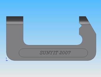
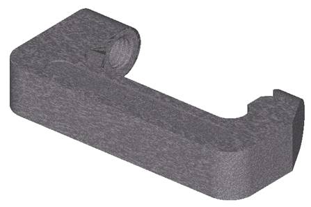
For my project I chose a C-clamp frame that I created using Solidworks for another class. Initially, I tried to draw the basic shape of the c-clamp frame and then extrude it. However, I found it very difficult to draw the shape to its desired specifications.
I then tried to draw the shape in Solidworks and then import it into Microstation and then extrude it. Solidworks was unable to create an IGES file with just a sketch of the shape.
Next, I tried to import the basic solid of the c-clamp without any of its features such as the thread hole or fillets. Microstation wouldn’t allow me to create any fillets on the imported solid.
Finally I ended up importing the c-clamp frame in its entirety from Solidworks and then working on the rendering effects in Microstation. I still had difficulty however in the initial placement of the c-clamp frame after importing it into Microstation. What was supposed to be the front view of the object ended up being interpreted as the top view in Microstation. I was unable to correct this, so I had to rotate the views of the image until the object was in the general area of the way that it was supposed to be presented.
Thomas
Kopec. (Civil Engr. Technology)
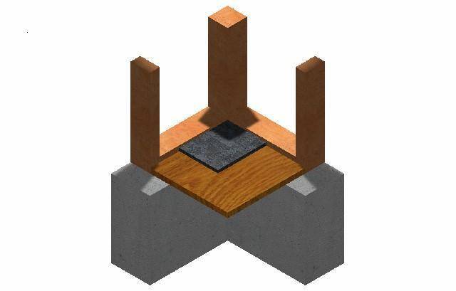
The drawing I constructed for my final project is an isometric view of a residential wall & floor section. The view displays a corner section showing part of the poured concrete foundation wall supporting a 2x6 sill plate, 2x6 vertical wood framing, plywood sub floor and a section of marble tile floor. The creation of the drawing in 3-D was not that difficult when I keep my drawing constructed of 3-D primitives.
The 3-D primitive that I used was the slab feature and then I began connecting the slabs together to create my drawing. My drawing was set-up by creating a layer for each material that would be rendered in the drawing; this technique made the rendering process a whole lot easier. I said easier because my first drawing was constructed line by line and when I was finished and ready to render I could not render the drawing properly. Having had great difficulty rendering the first drawing I was forced to start my drawing over again.
The light source that I used in my drawing was a spot light placed 90 degrees above my image so it brightened the center of my drawing and also cast a shadow of the vertical framing members across my drawing. Overall I found the rendering process to be difficult at first but after repeating the process a number of times I began to understand it better.
. 
Mattydale
Fire Department Rendering
Nathan
Van Wie (Civil Engr.
Technology)
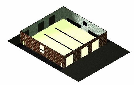
The final project I chose is based on a project that I am currently working on in the professional field; it is the Mattydale Fire Department 3 apparatus bay addition. This rendered image only represents a small portion of the actual project. I used an actual set of plans to construct the image.
The image is of a masonry wall structure with a brick façade. It is approximately 30’ high. It contains three overhead doors on both the north and south side of the building. The doors are approximately 18’ high by 14’ long. On the west side of the building there is one large window and two man doors. The pattern repeats itself on the west side of the building. The primary difference is that the window is a half window roughly 5’ of the floor. The interior doorways are open archways. The east wall of the building also contains two sets of equipment racks. They are 2’ off the floor and 3’ high. The slab on grade is 6” thick, there are 3 trench drains located in the center of each overhead door. There are asphalt approach aprons on the north and south side of the building. A cobblestone walk is located on the east and west sides. On the east side of the actual project would be the rest of the building. The roof of the structure was left off intentionally to show some of the interior details. The added light is intended to represent car headlights one the northwest corner of the building.
The most complicated part of this project was rendering the image. The first time the image was rendered I used smart line and created 3D blocks. I then tried using slabs and found that rendering was much easier. I erased the entire image and began drawing the image using 3D primitives. Once I had the structure drawn, I had to combine the slabs to create corners. This was fairly easy to do. The process further complicated with addition of several doors and windows. I attempted to leave one door open on the front and show the other two as closed. This failed horribly and I ended up recreating the front wall of the building. I also attempted to use glass to create windows in the doors. Once again after many frustrating hours I decided to scrap the overhead doors and just left the front and side of the building without doors or windows.
Overall the project was both challenging and frustrating. Working in 3D is going to be a vital part of engineering in the very near future. It allows clients and engineers an in-depth look at how the final project should look when completed. It could mitigate discrepancies or dislikes by both parties and will greatly increase the success of many projects.
Brian
Parker (Civil Engr. Technology)
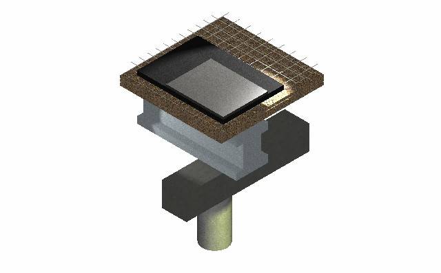
I opted to make a 3-d drawing of a cutaway section from a concrete steel bridge. I found this picture on the internet and since it related to civil engineering, it seems like the appropriate choice. Composed primarily from 3d primitives, I had to draw the I-beam in 2D and then extrude it to the desired length. To make the mesh grade, I didn’t make it exactly like the picture from the internet showed. I made a line, copied that line a few time in one direction, and finally rotated it ninety degrees so I could copy it a few more times. The end result was close to what was on the original but not exactly the same.
One problem I encountered was trying to render my drawing. At first, when I tried rendering one piece on the whole drawing, it would make everything that material I had selected. I didn’t realize that each piece of the bridge had to be on a separate level in order to render it. Another small problem I had was getting the lighting just the way I wanted it. After changing the intensity of the light and the color to yellow on one of the spotlights, displaying my drawing was better than having it rendered only. One spotlight even showed that the I-beam was not just a solid square block by highlighting and creating shadows.
Bradley
Gates (Civil Engr. Technology)
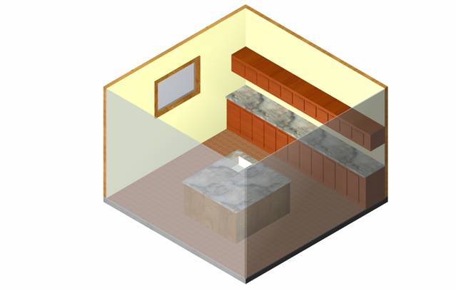
For my project I chose to draw and render a simplified portion of my kitchen. I wanted to show the kitchen as a section, so I treated the cut lines as a sheet of glass. The kitchen is built on a concrete slab and has hardwood floors. The island is made of a slab and the countertop is a slab placed on top of the island. The sink was then cut into the island using difference tool. The countertop was rounded using the chamfer tool and then rendering was complete. The walls are made of a slab and then rendered according to the face that is showing. The window was cut into the wall using the difference tool as well. I then added an additional slab inside of the opening to create a window. The trim was then added using the slab tool as well.
The upper and lower cupboards were created using the extrude command. A simple rectangle and square was drawn and then extruded along the line of the wall. The doors were then added using the slab command. Once I made one of each I used the copy command to line the length with doors and the align face command to place the doors in the proper place. The cupboard countertop was added using the slab command and chamfer command to round off the edge. A slab was then added on each face that was to be shown as the cut line. The slab was then rendered as frosted glass.
The most difficult part of the project was getting all of the glass slabs render so that they were all clear. If all of the faces are not clear then a refection is shown on the glass that is not wanted. The next hardest was having things line up and created in the actual place that you wanted, and not snapped to another line or object along the same line. The use of the different views was very important.
Josiah
Tabolt (Civil Engr.
Technology)
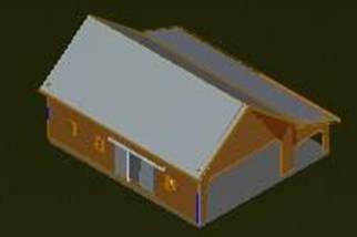
The object I chose to draw was an older barn I found online. I made the foundation to be a concrete slab. At first I tried to make the walls appear to be an older looking wood. I was not really happy with the way it looked so instead I choose a more vibrant color, making the wood appear new and more realistic looking. There is no interior to this barn just the outside shell. The picture depicted the inside of the barn to be black. I had a difficult time achieving this deep color that was desired because it showed the colors slab below or the walls behind the openings. The windows were also difficult because I was trying to make them appear more reflective than transparent. I made the window frames, the door, and the door holder, stick out of the barn to give it a more realistic look. I wanted the roof to look like a tin roof, which took a while to find a hatch where I would be able to achieve this.
My biggest mistake was probably not drawing this with slabs. When I tried to attach my layer/s, it was very difficult to select the correct object I was intending to attach it to. Although I feel it would have been easier with slabs, I found much success in drawing everything in layers. Than when I wanted to attach, say my wood to the outside wall I would just turn off all the other layers and select that shape. Also to help make my barn look more realistic I placed a slab underneath it and placed a grass layer to it. As far as lighting, this helped a great deal. I selected a daylight lighting to make it appear as though the sun was shining on it. This cast a small shadow on my roof changing the shading a little. I didn’t want to place any light shining directly from one side because that would not really be the case with most barns, unless it was at night. The overhangs from the roof were also difficult to achieve because it slants out past the wall. It was hard to make this symmetrical all around the building. I ended up drawing the outside structure first and than drawing using hidden lines to give me bearings on where I was suppose to place my actual walls.
Michael
Wechsler (Civil Engr. Technology)
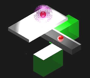
I chose to make a glass ball due to the interest it gave me, and the aspects of transparency that could be beneficial to future project. All objects are 3D primitive elements. To create the glass ball effect, I place 3 spheres closely inside of each other. Under element attributes I changed the color and transparency. The outside sphere was changed to 80% transparency, the middle sphere to 90% transparency and the innermost sphere to 50% transparency. The final part is to apply positional lighting to emphasize the glass ball.