CTC
312 – Microstation V8XM
Student
Examples of Rendered Drawings (Spring 09)
Justin
Bator (Civil Engr. Technology)
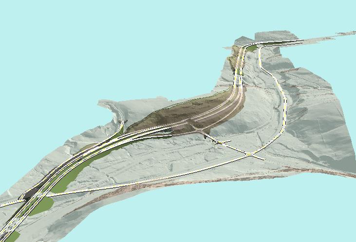
For the Microstation Final exam/final project I chose to use something work related here at Lochner. The images provided were brought to a NYSDOT meeting recently. The specific software utilized was Microstation and ArcGIS. Particularly in Microstations the extension of Inroads was used and in ArcGIS an extension of ArcScene was used for the capture of the imagery. To start off the imagery shown above shows an existing ground surface model colored in a grayish tint. Then the proposed modeled surface is in green, dark grey, proposed edges of pavements and striping. The existing surface is transparent so that we can visually see and determine where the cuts and fills will be located along the proposed roadway. Directly in the center of the image we see the transparent ground surface which the proposed roadway is into therefore the hillside will need to be removed in order to place the new alignment.
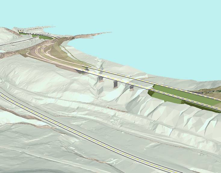
The second image above shows viewers the concrete abutments and piers for a bridge that will carry the new alignment over multiple ravines. On the right side of the image we can see that there is a need for the road to be in a filled state, but after the roadway crosses the bridge we see the ghost like shadowing of the existing surface. This is where the existing ground is in need of major cut. The total man hours put into the surfaces is unknown but given the detail and project parameters I would guess it would be somewhere in the thousands of hours. In order to complete this visual simulation in 3D and capture the imagery shown here my time was around the 25-30 hours into this project.
Tom
Flynn (Civil Engr. Technology)
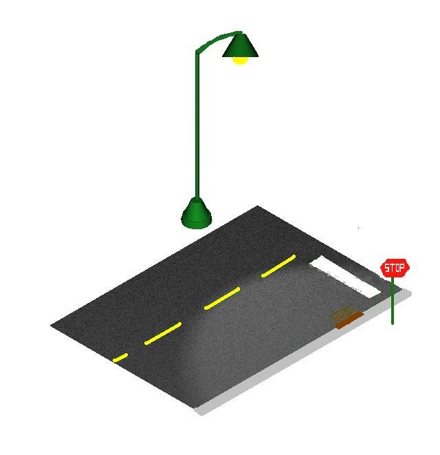
For my final project I decided to draw a section of a traffic intersection. The drawing includes a stop sign, a light post, a sewer grate and a section of road. The drawing contains source lighting from the light post making it a night scene. The most difficult part of the project was figuring out what view to capture. After some trial and error, the right isometric view was selected for use throughout the drawing. Using some basic shapes, the sketch of what I wanted to create came to life. Another hard part of the project was getting the rendering the way I wanted it. Numerous times shapes would overlap, refuse to be rendered, or when rendered just turn to green when saved as an image. Otherwise the project went well.
Ryan
McHugh (Civil Engr. Technology)
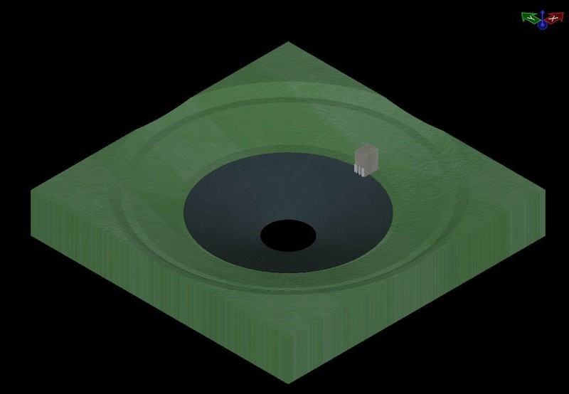
For my final project I designed and drew a detention basin. The design is from the book Introduction to Hydraulics and Hydrology 3rd edition, ch. 15 number 6. The basin is a spherical open-cut design with a gravel base. Its dimensions are 6ft deep with a top radius of 39ft and a base radius of 6ft. It has a volume of 3050 cubic feet. Located within the basin, there is a two stage outlet system.
Troy
Barnes (Civil Engr. Technology)
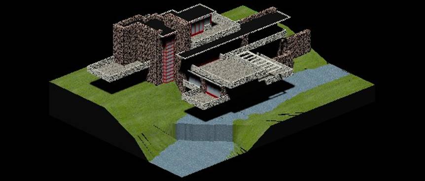
Frank Lloyd Wright is one of my favorite architects and ‘Falling Water’ is one of the most famous residential buildings. I thought it would be neat to render it, because of all the levels and columns of stone.
I imported a floor plan of the house and redrew it in two dimensions and then used the 3D modeling tools to extend them up to three dimensions. I did one floor at a time until I had the whole structure. After placing material on the building I started on the landscaping. The landscaping tapers down towards a stream that has a waterfall at the corner of the house. I used a lot of Surface Modeling tools to draw the river banks and waterfall.