CTC
312 – Microstation V8i
Student
Examples of Rendered Drawings (Spring 11)
Eddi
Rizzo (Civil Engr. Technology)
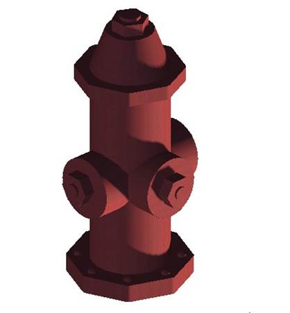
For my CTC 312 (MicroStation) Final, I chose to make a three dimensional model of a fire hydrant. I chose this simply because I was hung up on ideas for the Final, and Professor Baran happened to say she would like to see someone attempt a 3D fire hydrant.
In order to create the model, I utilized several commands learned throughout the semester. Such commands include, but are not limited to: Place SmartLine, Place Line, Place Block, Place Rectangular Polygon, and Place Circle within the Drawing Toolbox; Solid by Extrusion, Fillet Edges, and Mesh from Element within the Solid Modeling Toolbox. After constructing the model, I utilized the Render Toolbox and Light Toolbox to add a realistic appearance. These two toolboxes may be found under Tools, then Visualization.
I found it very frustrating to get an entity to extrude in the desired direction. I actually ended up drawing the entire model up-side down. I found it surprisingly easy on the other hand, to render and apply all sorts of lighting. This is likely due to the fact that I had to do my Presentation on the topic of lighting, so I familiarized myself with all aspects of lighting MicroStation has to offer while in the midst of developing my model.
Ryan
Myers (Civil Engr. Technology)
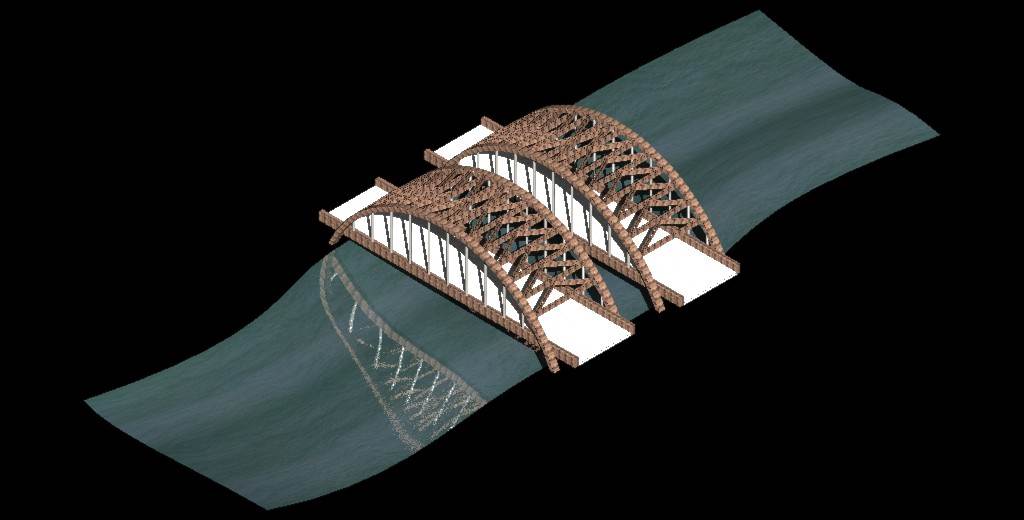
I chose to draw the Twin Bridges that span the Mohawk River on Interstate 87 also known as the Adirondack Northway. The bridge’s real name is the Thaddeus Kosciusko Bridge and spans between the Town of Colonie, Albany County and Halfmoon, Saratoga County. They are located between exits 7 and 8 of I-87. I chose the bridges to draw because they are well known throughout the Capital District and I have traveled over them many times. The bridges carry 6 lanes of traffic total, 3 northbound and 3 southbound. The company I’ve worked for during the summer, DA Collins, built the bridges back in the 1950’s and they became the signature logo for the company. The bridges were kind of tricky to draw with the cross bracing following the curve of the arches. I used block surfaces to draw the members of the bridges and bridge deck as well as the arcs for the arches. I created as surface for the water of the river using splines and a surface placed based on points. Applying the materials to the surfaces and rendering the image were rather simple to do.
Tim
Zotta (Civil Engr. Technology)
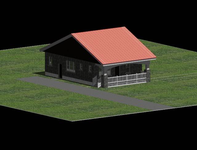
I decided to do a rendering of my house. Reason being, I am planning on redoing our front porch. Currently, the stairs come off the front of the porch in the center but because we have a steel roof, the snow comes shooting off it at lightning speeds once the temperature gets much over freezing. The snow pushed our chimney off our roof on Valentine's Day this past year, imagine what it could do to someone’s head while they were walking up the stairs on my front porch given the right timing. This is why I am planning on putting the stairs where they are in the rendering. Getting back to why I chose my house, my wife is a very visual person. Initially she did not like the idea saying,” It won't look symmetrical" but after rendering the house with the "fixed" front porch, she agreed that it didn't look bad and it was the best decision. First, I drew a complete primitive of the entire house and then applied surfaces by corner points. The most difficult for me was figuring out how to actually apply the materials. Initially, it gave me some trouble. I set up the lighting according to solar light position based on our latitude and longitude coordinates in Utica, New York. The house is drawn true to scale. I took rough measurements of the entire house as to the corner points of the house and the window and door placements. Even though it was time consuming and at times frustrating, I enjoyed this project and the subsequent outcome, a true to scale rendering of my house with the fixed porch entrance.
Cesar
Pimental (Civil Engr. Technology)
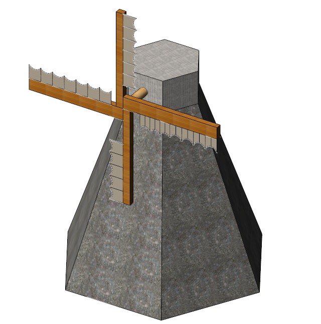
One of the hardest parts of this final project was deciding what I wanted to draw. I eventually chose a Dutch windmill because it looked simple, yet it had a certain degree of difficulty. I composed this drawing by starting from the inside out. So first I created the main body of the windmill by using the solids modeling tool to create a six sided pyramid. Using certain edges of the pyramid and grid lock, I started attaching other objects to the main body to make it look like a windmill. I then created a surface area to whatever object were two dimensional so that I could apply materials later on. Then, I attached the materials. In order to give me a better view of what I was drawing, I switch the view to Illustration. This makes the materials that you apply visible without having the render the image first. I then applied lighting. The lighting I chose was natural sunlight at 4:00pm. The last steps are rendering and saving the image as a jpeg.
The easiest part of this project
was placing the first couple of elements, placing the lights, rendering the
drawing, and saving the image. The hardest part was aligning certain object to
make them a certain way. Because there are only so many views, I sometimes
found myself placing an element that looks right and aligned on one view, but was
distorted and crooked on another view. Another difficulty I experienced was
adding detail to my drawing. Because it can be hard to manipulate the smaller
lines and elements, I found myself omitting certain things.
Reimy
Tejada (Civil Engr. Technology)
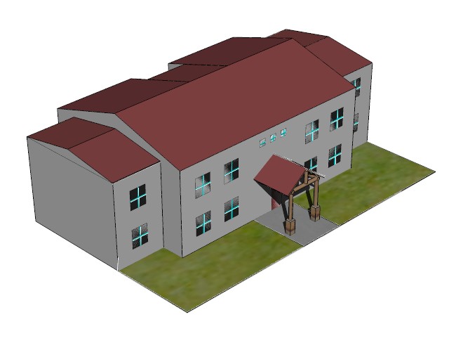
For my final exam, I chose to draw one of the buildings from ADK, building B. I started off with this project by scaling the building using a picture of the building taken from Google Maps. The structure of this building is composed of basic figures of geometry. To construct this building, I created four 3D dimensional rectangles and on tap of each rectangle I created two 3D dimensional triangles. Afterwards, I united the rectangles to form the final shape of the building. The final result of this project includes windows, grass, a door, and a front porch. Once the structure of the building was completed I applied materials to all surfaces of the building. One of the most challenging parts of this project was trying to add materials to the building. I couldn’t find the exact color for the outside walls. Another problem that I faced while I was creating this building was that I couldn’t find a way to build the front porch. It took me more than an hour to find out how to construct the front porch. Over all, I chose to build this building because I knew it would be challenging for me and I it was.
Nadia
Vedder (Civil Engr. Technology)
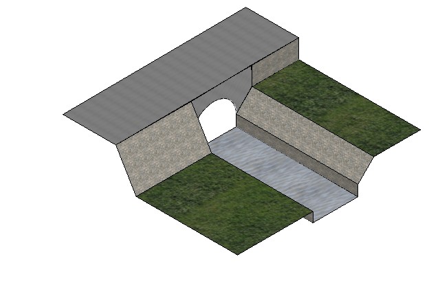
For my final project in MicroStation, I decided to try to duplicate one of my favorite locations on Bucknell’s campus. This was along the creek that ran through part of campus; it was right outside my freshman dorm and one of my go-to study and relaxation areas when the weather was nice. I thought it would make an interesting area, since it did have a culvert, and several different types of materials (with the concrete, grass, water, and riprap). One of my difficulties at first was getting the water for the creek to render correctly. After much experimentation, I finally found a result I was pleased with. I also had a lot of difficulty trying to get everything drawn on the correct planes; this again took quite a bit of trial and error. I also had trouble at first getting the culvert drawn the way I wanted it to be; I finally found the “trim surfaces by curves” feature which is the exact tool I needed to accomplish this. While this is a relatively simple design, I’m very pleased with the results considering where my skill level was at in the beginning of the semester.
Michael
Pilling (Civil Engr. Technology)
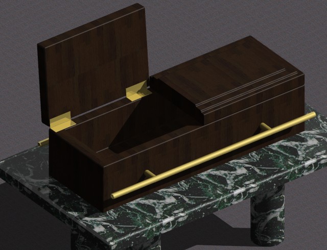
I chose to draw a coffin. It is not the most complicated drawing, so I
added a marble table to add to the detail of the rendered image. To start this project, first I drew all of my
solids, then went back and cleaned up the edges. To keep this project simple, I created all
objects as solids, rather than surfaces.
I started off by under the solid modeling and created a slab solid. The slab turned out to be the top of the
table. For the four legs I added four
cylindrical solids below the slab. These
connected the table to the perceived floor around the image. I also used a slab solid to create the coffin
as well. In order to give depth to both
slabs I used the solid by extrusion to extend coffin and table top into the
Y-axis. This command also allows the
user to cut into an object. This gives
the rendering a perceived 3 dimensional box that the viewer can see. In order to see the full effect of this
command I made the door of the coffin to be prompt open. After all of these processes were completed
the rendering had just a rough 3-d look.
To give the coffin character, I tapered the edges of the coffin, inside
and outside, to give it authentic look.
I also added hinges to the side of the coffin is well. I smoothed out all my surfaces to give the
coffin a clean finished wood look. Now
the object looks better, but it needs a materials assigned to the rendering. I had to load a marble and wood pallet first,
and then I placed the accompanying material to my 3-d solids. Because the coffin is open, in the real world
there would be a shadow cast down into it, so I added a light from the place
light command at a shallow enough angle to cast shadows within the coffin. I also stepped up the detail on the coffin to
give it a shiny look like wood that has a few coats of polyurethane.
In order to keep this project simple I stuck to simple
shapes, materials, and shadow options.
There were a few problems I had when it came to adding material:
sometimes it just wouldn’t appear. But
the more difficult problem was the lighting.
Every time I tried to add light for a shadow the huge rendering would go
completed white. I had to ask a few
questions, but got help on it. Overall I
could have done something more complicated, but still I like the look of the
final rendering and most importantly, I feel more comfortable with rendering in
3d files.
Stephen
Sherwood (Civil Engr. Technology)
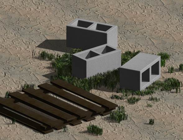
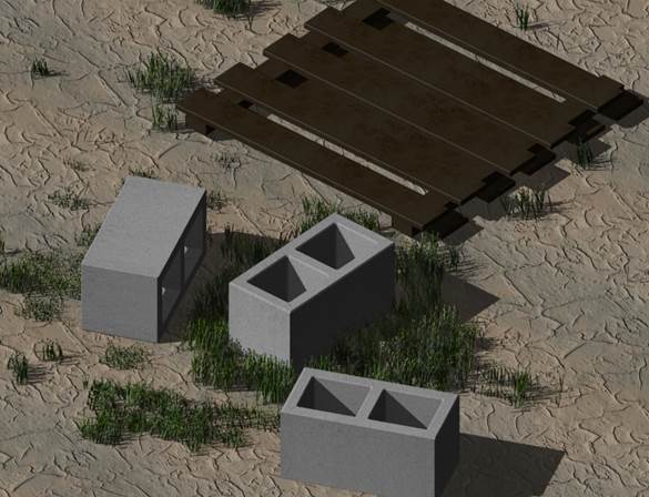
My drawing consists of three CMU blocks and a wooded pallet. The grass was used to fill empty space and each blade of grass is rendered independently of each other. The grass was made by making a few blades then changing the height and position at random. I did attempt to place a back drop on the drawing with the use of a custom texture but due to difficulties placing textures in the proper position the idea was scrapped. All the basic 3D commands were used and the whole setup is drawn as a solid. Rendering and texture utilized bumping features in the material dialog box.
Tim
Brown (Civil Engr. Technology)
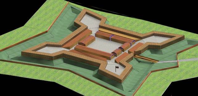
For my Microstation final I decided to combine my love of history and Civil engineering and rendered a to-scale replica of Fort Stanwix in Rome New York. Fort Stanwix is a classic example of a Star fort. This fort design was a prominent and dominant design first deployed in Europe and then making it way over to the new world where it was deployed in the “wilderness”.
The rendering is based on a survey of the fort’s foundations and the original plans of the fort from the United Kingdom’s National Archives in London. The rendering includes a large flat open area as you approach the fort. This open area dumps into a 6 foot deep by 40-foot wide trench that surround the fort on 3 sides. The main defenses of the fort are 13-foot high timber and earth rampart system that in its day held an array of cannons. On the interior of the fort I re created the two barracks, the officer’s head quarters and the fort’s bake house. I also recreated the 4 casements along the inside walls of the structure; these casements acted as the store for the forts weapons and munitions.
The drawing I created was done using stick drawing technique we learned for the midterms. I then used the stick frames to lie out the different surfaces needed on individual layers. This technique allowed me to develop the sloped look of the grounds around the fort and the separate elevations needed inside the fort itself.