CTC
312 – Microstation V8i
Student
Examples of Rendered Drawings (Spring 13)

Jami
Russell (Civil Engr. Technology)
For the final project, I wanted to do something complicated to exercise my skills in microstation, but not too complicated that it was overwhelming given the time frame. My original thought was to construct a sprint car frame, as that would have been useful to me. Unfortunately, that would have exceeded my skill level in 3-D modeling and would not have been feasible given the time limits. Instead, I decided to model a sprint car wheel. I’ve got several kicking around my shop, and it is something that I could more or less duplicate from memory.
Originally, I was going to include the gold anodized center hub as a part of the project, but after about 3 hours of playing with it to get the profile and the shape right, I ended up scrapping that idea and decided to just stick to the wheel as it bolts to the hub, including the bead lock and the bolts. The command that really threw me with the center section was the “subtract solids” command. I must not have had a true shape recognizable to the computer because it wouldn’t recognize the shape as a solid and wouldn’t let me manipulate it as such.
To construct the wheel shell and the bead lock, I simply created the section to scale in the top 2-D view, and used the solid by revolution command to develop a circular shell. The devil was certainly in the details as there was a significant amount of time invested in getting the tire bead surface the way I wanted it and getting the radius’ to look correct. Once I got all of that together, I extruded some bolt shafts to connect the wheel shell to the bead lock and created a bolt head, then used the array command to pattern them correctly around the wheel. This was an instance where my knowledge of an actual wheel was helpful. It was important to get the right amount of bolts in the wheel and have the spacing be correct. The portion of the wheel that bolts to the hub has 15 bolts on a 9.75” circle and the bead lock has 16 bolts around the ring. I set the wheel shell and bolts as a polished aluminum material, and the bead lock as a dark red material. I had a hard time getting the colors to show up correctly in the rendering, but it still ended up looking ok.
Michael
Stevens (Civil Engr. Technology)
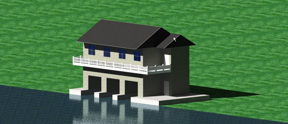
I choose to construct a boat house for the culminating project for the spring 2013 MicroStation Class. I began by drafting a house from scratch and working out the dimensions. I then created several ‘layers’ of 3 dimensional blocks to give the house depth and a modern build. A wrap around deck was also added to give a horizontal to the house horizontally, adding to the appeal. The decision to build a boat house called for several materials (7+) to be chosen and added to the structure giving it a realistic appearance. All elements of the structure were carefully placed and drawn to a realistic scale. The drawing proved to be both daunting and rewarding. Constructing some elements of the drawing, including the deck and boat garages, took several hours as they required working in 4 different views in order to string lines together and remain on the proper plane. All in all the drawing turned out to be a success and a motivation to draw more complex structures.
Laura
Layton (Mechanical Engr. Technology)
Why I chose this
drawing, how I composed it and what I found easy or hard to do….
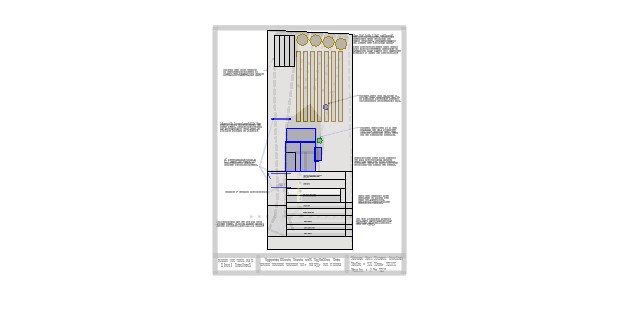
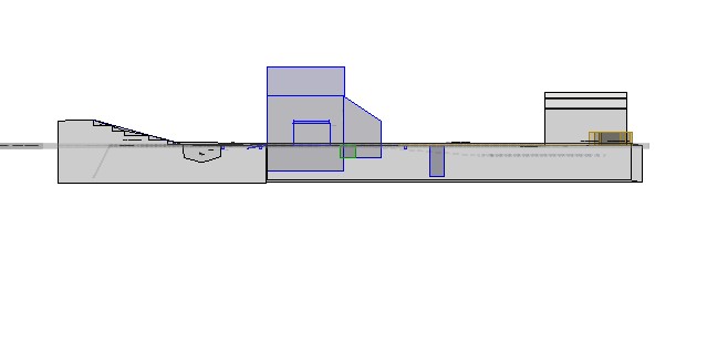
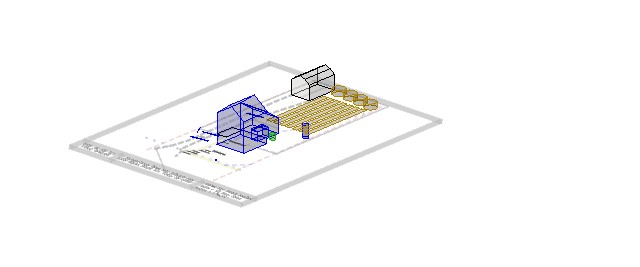
I chose to do a three dimensional image of my house and property with
the addition of future renovations to the property to include a small scale
fish farm and greenhouse, using the land available to me and the list of
materials below to develop this 1/3 acre into a semi-commercial operation. My husband and I recently purchased this
property at a bargain price and the renovations required to bring the home up
to code will entail many man hours as well as a lot of financial
investment. While we are doing this, we
are living on one income and I am going to school at SUNYIT full time. My passion is gardening and renovating homes
and my husband is the cook. We agreed to
raise fresh vegetables and Tilapia on this property to justify my plans for
renovations and to feed ourselves and our friends.
The existing barn is not useable until the foundation has been
replaced; this is why I am focusing on a mainly outdoor operation. As funds
become available, and the house is renovated, we will be turning the barn into
a two car garage with music studio upstairs. This is of course only if it does
not collapse before we can complete the renovations……..
My Plans include:
· Digging and lining a pond in the front yard where the water table is high
and runoff collects from the renovations the town of Clay has done to the existing
highway.
· Smoothing out the existing driveway, digging culvert ditches (3locations)
and installing culverts and crushed stone on top, rolling with machinery to
compact the driving surfaces.
· Smoothing out and installing tiers in the front yard to be pathways for
the lawn tractor and planting beds for the initial farming stage.
· Planting apple trees, raspberry bushes, strawberry beds and such for
future harvest
· Rooting and planting willow tree cuttings along the western edge of the
property where water runoff tends to collect and drainage needs to be improved.
· Building fish tanks in the back yard for next year’s Tilapia harvest.
Since they take approximately 8 months to grow to marketable weight, The first batch of hatchlings will be purchased in May of
2014, with expected harvest in December.
· The front yard pond will be my “training” pond and I am expecting
construction to be complete by July of 2013, with Goldfish as my main fish to
use since they are cheap and easy to handle.
· Future plans for greenhouse to cover most of the back yard, including but
not limited to the entire Septic Drainage field area as illustrated. Raised
temporary beds to be used in case I need to repair the septic lines and the
plants will not use septic or draw from the field and will be watered solely
with fish water and fish waste.
· NO PESTICIDES, HERBICIDES, ANTIBIOTICS or other artificial chemicals will
go into the production of any fish or vegetable plants. Water from the city of Clay will be used to
replenish the existing tanks as necessary only after it is filtered,
de-chlorinated and tested.
This drawing was produced mainly using
Bentley Microstation®, Microsoft Paint® and Microsoft
Word® to gather all the images and incorporate them into the final
product. I am just learning Microstation® and have found that I do not appreciate the
intricacies and peculiarities of the program.
I feel that a lot more time would be necessary to master this program in
order to be effective in my engineering career.
When printing out the project, the print preview looks perfect and the
actual print has ghost images on it, making it quite frustrating to work
with. I enjoyed working in three
dimensions and find this as easy to do as in AutoCad®.
I have to credit Mark Doherty of Aquavita Farms in Sherrill, NY, who is a graduate of SUNYIT
and runs a successful 100% indoor Aquaponics farm
operation. I met him last month and he is an inspiration to me. I was able to
tour his facilities and was quite inspired by the methods and excitement he
offered to us all in educating us about the use of Indoor Fish farming in
conjunction with hydroponic growing of salad greens…. I had never seen so much
lettuce in my life. I would have loved
to have met him last year when I did a research paper on Aquaponics
for my SUNYIT Communications class.
Evan
Hala (Civil Engr. Technology)
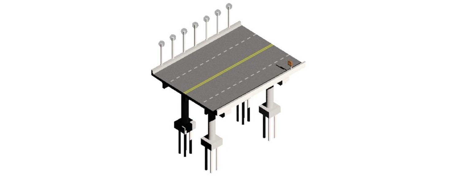
For my final project I chose to design a section of a bridge
and show a two lane road with shoulder guards and footers that hold the bridge
up. I started with the foundation, where the main support would hold the bridge
in place and keep it from moving. Second I started the main column groups that
hold the bridge up and connect them to the footings. Next is a beam that
supports the road and guards above. I had a pretty hard time when it came to
the rendering of the objects, it just didn’t seem to want to do what I wanted
and place the material, and it would always be a black material no matter what
I chose it to be. Also when I would attach the material it would be distributed
across the entire object instead of just a face or separate object. As I had
time to change different options, I learned that if the model space is set to
monochrome none of the materials or attachments will show so it needed to be
changed to a modeling view instead of monochrome. The rest of the project was
fairly easy such as chamfers, making 3d objects, and extrusions. I placed a
roadway sign and light posts on the section of road to show the ability to place
lights and show more visual sides that would otherwise be dark.
Bernard
Zahn (Civil Engr. Technology)
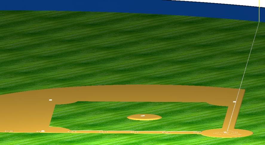
For my Microstation final, I chose
to draw a baseball field. I had a few ideas including a tunnel over the Campus
Center Bridge as well as Donovan. The baseball field seemed like I would enjoy
doing it more at the time. The baseball field I did was drawn with Yankee
Stadium in mind.
To create the field into solids, I had to use smart line many
times to get single shapes. Once I had the shapes all set up, I used Solid by
Extrusion to different heights so all would match up well. In some places I had
to use Fillet edge, like around the edge of clay, so things lines up more
smoothly.
I was very accurate in
planning out the field and measurements are exact matches to a major league
field. The infield grass is 2 inches higher than the dirt, the base are 3
inches high, the baselines are 90 feet, and even the rubber to home plate is
60’-6”. I wanted to be very exact with the dimensions because it is something I
have a lot of care in. I set up the field so center was north, and home plate
was south. This allowed me to set up the sun in a location I wanted to show off
the grass, dirt, bases, and outfield wall just the way I wanted to.
I was very happy with the results and feel as though I could
design an entire stadium with more time. This is something I would like to do
in the future so getting my feet wet with this project may help me down the
road.
Tanner
Metzko (Civil Engr. Technology)
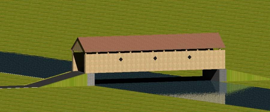
This drawing has been accomplished by using MicroStation V8i, a Bentley engineering software program.
Over the course of the semester our class has familiarized ourselves with just
the basics of this extremely broad program. This drawing portrays a covered
bridge located in Delhi, New York called “Fitch’s Bridge”. The bridge spans
across the Delaware River and was constructed in 1885 at what was known to be
“Fitch’s Crossing” at the time. Being only ten minutes away from my home,
driving past this historical structure became a daily encounter. Even as a
child I always admired this bridge, but now as an adult and a student in the
Civil Engineering field I have come to appreciate structures such as this one.
Despite the technically advanced engineering used in bridge construction today,
the aesthetics of a covered bridge are hard to come by. The old, rustic, and
weather-beaten look of a covered bridge is simply beautiful in my opinion, and
unfortunately few of these structures still stand today. In the past few weeks
I have told several peers about my final project, a drawing of a covered
bridge; several of those peers had not heard of or seen a covered bridge. That
goes to show that a historical landmark such as Fitch’s Bridge really is a
privilege to see.